This website contains content related to firearm components and building tools. Access is strictly limited to persons of legal age according to their jurisdiction. By entering this site, you affirm and certify the following:
1. I am at least 18 years old for long gun components 2. I am at least 21 years old for handgun components 3. I am NOT a prohibited person under federal law (18 U.S.C. § 922(g)) 4. I am in a jurisdiction where accessing this content is legal 5. I understand that misrepresentation may constitute a crime
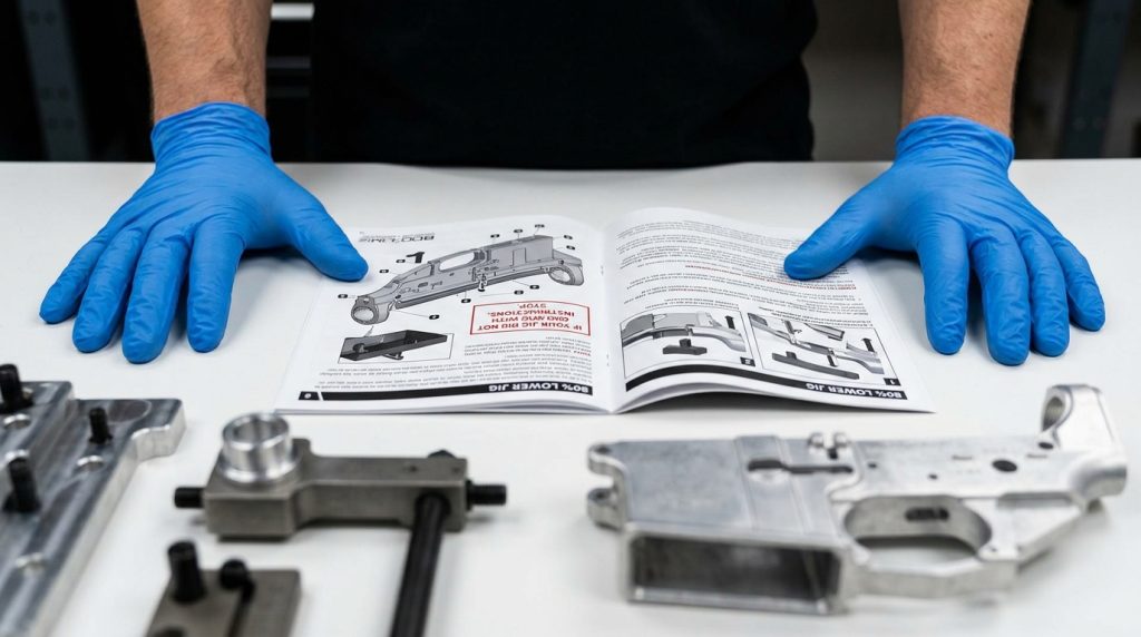
An 80% lower jig is not complicated equipment. It’s a precision fixture — a block of machined aluminum or steel with guide holes and stops positioned exactly where they need to be so that you drill and mill in the right places, at the right depth, every time. The jig does the navigation. You provide the machine and the patience.
What makes beginners struggle isn’t the jig itself. It’s setup errors that compound through the process: a lower that isn’t fully seated, a depth stop set 1mm too shallow, a bit that was cheap and flexed under load. This tutorial walks through the complete process in workshop sequence, addresses the mistakes that actually happen to first-timers, and gives you the honest version of what to expect — including what can go wrong and how to recover.
By the end, you should be able to walk into your workspace, set up your jig correctly the first time, and complete your lower without surprises. Let’s get into it.
Table of Contents
What You Need Before You Start
Get all of this on the bench before the lower comes out of the bag. Running to find a tool mid-process means losing focus at a moment when focus matters.
Required Tools
• 80% lower jig kit — matched to your specific lower receiver
• Drill press (preferred) or corded hand drill with steady technique
• Carbide end mill — size specified in your jig instructions (typically 5/16″ or 3/8″)
• Drill bit set — sizes specified by your jig (usually included in quality jig kits)
• Cutting lubricant — any light cutting oil, applied generously to bits before each pass
• Rubber mallet and punch set — for any alignment pins in the jig
• Hex keys / Allen wrenches — for jig clamping hardware
• ANSI-rated safety glasses — non-negotiable, worn before any machine starts
• Work gloves — for handling the lower after cutting (edges are sharp)
• Shop vac or compressed air — for clearing chips between passes
• Bright work light — overhead lighting casts shadows exactly where you’re working
⚠ HEADS UP: Eye protection goes on before you touch the drill press. Polymer and aluminum chips travel fast and far. This isn’t the reminder you paste at the bottom of the article — it’s the first thing you do when you walk to the bench.
STEP 1 Read the Jig Instructions for Your Specific Kit
This is not a generic tutorial disclaimer. Jig kits are not all the same, and the instructions that came with yours contain specific depth settings, bit sizes, and drilling sequence details that differ between manufacturers and even between jig generations from the same manufacturer. Read them completely before touching anything.
What you’re looking for in the instructions: the exact drill bit diameters for each hole, the correct depth stop settings for each pass, the order in which holes are drilled, and any notes about your specific lower receiver that affect the process. Mark those depth settings down somewhere visible. You’ll be referring to them repeatedly once you’re under the lights with a drill running.
If your jig kit didn’t come with instructions, or the instructions are unclear, stop. Download the manufacturer’s guide from their website or contact the jig maker before proceeding. Starting a machining process without clear parameters is how expensive mistakes happen.
STEP 2 Secure the Lower Receiver in the Jig
Lower placement is the most critical setup step, and where most first-timer errors begin. The lower needs to be fully seated against all reference surfaces in the jig — any gap, any twist, any rock in the fit will translate directly into an off-spec finished product.
Place the lower into the jig body and verify it’s fully bottomed out in the receiver channel. Check that the front takedown lug area is properly seated against the jig’s front stop. Tighten the clamping hardware finger-tight first across all points, then bring each point to final torque in sequence — the same way you’d torque bolts on an engine. Snugging one side hard first can introduce a slight twist that you won’t see until the drill bit tells you something’s wrong.
Once clamped, attempt to rotate and rock the lower by hand. There should be zero movement. If you can feel any flex or shift, stop and re-seat. This step takes five minutes done right and costs you the whole lower done wrong.
⚠ HEADS UP: Do not assume the lower is seated just because it looks level. Physically test for movement after clamping. Polymer lowers are especially prone to seating errors if the jig channel has minor dimensional variance.
STEP 3 Set Your Depth Stops
Every drilling and milling pass on an 80% lower has a required depth. Go too shallow and the fire control group won’t fit. Go too deep and you’ve removed material that the design requires for structural integrity or component function. Your jig instructions specify the exact depth for each pass — set your drill press depth stop (or mark your bit with tape if using a hand drill) before the bit spins.
On a drill press, the depth stop is typically a collar on the quill column with a lock nut. Lower the bit to the correct depth manually, set the stop, lock it, then raise the quill back to the starting position. Test the depth on a scrap piece before committing to the lower if you have any uncertainty.
If you’re using a hand drill, the tape-on-the-bit method is workable but demands more discipline. Apply the tape at exactly the right measurement, keep the drill perpendicular, and stop the moment tape makes contact. It’s more technique-dependent than a drill press depth stop, but it works with care.
STEP 4 Drill the Pin Holes
Most 80% lower jig kits require drilling the fire control group pin holes first — the trigger pin hole and the hammer pin hole. These are the smaller-diameter holes through the sides of the receiver that will eventually accept the trigger and hammer pins from your parts kit.
Drill at medium speed with cutting oil on the bit. Let the bit do the work — you’re guiding it, not forcing it. Withdraw the bit every half inch or so to clear chips and re-apply oil. If you feel the bit catch or the drill suddenly labour under load, stop immediately and check what’s happening before continuing. A catching bit is usually chips packing in the flutes.
After drilling each hole, verify it passes through cleanly by running the correct-diameter punch through by hand. It should pass with light pressure. If it’s grabbing, a light deburring pass with a round file or the drill bit spun by hand (not powered) will clean it up.
STEP 5 Mill the Fire Control Cavity
This is the step that actually opens up the fire control group area inside the lower — the rectangular pocket where your trigger, hammer, and disconnector will live. It’s the longest step and the one that requires the most attention.
Install your end mill in the drill press or drill. Apply cutting oil. Lower the end mill to the starting position specified in your instructions — typically beginning at the front of the cavity template opening and working rearward in deliberate passes. Each pass should remove 1/16″ to 1/8″ of material at a time, no more. Aggressive passes generate heat, cause bit deflection, and produce rough cavity walls.
Work slowly and systematically. Clear chips between every pass with compressed air or a brush. Re-apply oil before each pass. Check your depth against the stop after every few passes. The cavity should look clean and consistent as it develops — if you see gouging, ridges, or uneven walls, slow down and check your setup before the next pass.
When you’ve reached final depth, do a light cleanup pass across the entire cavity floor at the correct depth. This evens out any minor variation from the progressive passes and gives you a clean, flat reference surface for the fire control components.
Patience on the milling step is what separates clean builds from problem builds. If it feels like it’s taking longer than expected — good. That’s you doing it right.
STEP 6 Finishing Touches
With drilling and milling complete, remove the lower from the jig and do a thorough chip-clearing pass with compressed air through every hole and into the cavity. Then do a visual inspection under good light: cavity walls should be smooth and consistent, pin holes should be clean and round, and the cavity floor should be flat.
Deburr any sharp edges on the cavity opening with a fine file or sandpaper. This prevents the edges from interfering with component installation and removes potential stress risers in the material. Run your finger along every interior edge — anything that catches a fingernail gets a light deburring pass.
Test-fit your lower parts kit before calling the lower complete. The trigger and hammer should drop into the cavity and pin holes without forcing. If anything binds, identify the specific contact point and address it with light material removal rather than forcing the part through.
What Can Go Wrong: The Honest Version
Every experienced builder has a story. Here are the errors that actually happen to first-timers, why they happen, and what you do about them.
Error
Why It Happens
How to Address It
Pin holes off-center
Lower not fully seated in jig before clamping
Minor variance — use undersized punch to check clearance. Major variance — the lower may be unusable. Prevention is the only real fix.
Cavity too shallow
Depth stop set incorrectly or never set
Return the lower to the jig and take additional passes to correct depth. Verify stop setting before continuing.
Rough / gouged cavity walls
Too-aggressive passes, dull bit, or no cutting oil
Light cleanup pass at correct depth usually smooths minor roughness. Severe gouging may cause parts fitment issues.
End mill walks at start
Starting the cut freehand without a pilot dimple or starting guide
Use a center punch to create a starting dimple before each milling pass. Keep initial entry pressure steady.
Drill bit breaks mid-hole
Cheap bit, no cutting oil, too much downward pressure
Remove broken bit with extractor tool. Use quality carbide bits going forward. Never force a bit under load.
Parts kit binds in cavity
Insufficient material removal or sharp internal edges
Identify exact contact point with blue layout fluid or marker. Remove material only at contact point with file or hand tool.
You Have What You Need
The jig process looks intimidating on paper and straightforward in practice. Setup takes the most time and deserves the most attention — a lower that’s correctly seated and a depth stop that’s correctly set will get you through the rest of the process without drama. The machining itself is just patience and light, consistent passes.
Take your time on the first one. The second build will go in half the time, and the third will feel routine. The jig is doing most of the work — your job is to not rush it.
Pick up the correct jig kit for your AR-15 80% lower at polymer80firearms.com. Kits include all required drill bits and end mills, installation hardware, and step-by-step instructions matched to the lower receivers we carry. Everything you need in one order.